MPO Cables - What are they and how do we use them?
Jun 20, 2023
I was recently chatting with a coworker talking through how we use MPO cables and various optics. It made me realize that I have a lot of “in my head” knowledge about fiber cables and optics from working in the networking space over the past 5 years or so, but I haven’t found a good reference point online to point people to and it would probably be better for that information to live written down somewhere rather than it just being in my head. So here it is - everything that is floating around in my head about MPO cables. I’ve done my best to double check what I’m writing here but it should be mostly accurate.
What is MPO?
MPO (Multi-Fiber Push On) in common terms refers to both the connector and the cable itself. It is a cable that contains (currently, 2023) either 8, 12, or 24 fibers terminated onto a single connector, male or female, on both sides of the cable. The cables are available in Single Mode (OS3) and Multimode (OM3, OM4, OM5) formats.
Where is MPO used?
For typical use cases, MPO cables are used in the following applications:
Multimode (SR) Optics - 40G and 100G
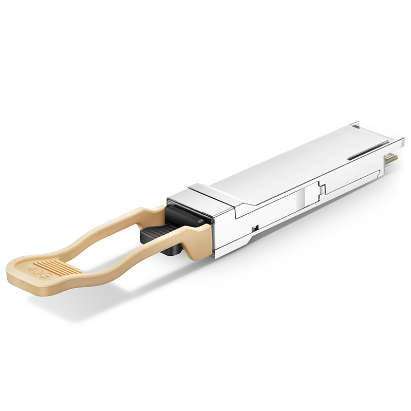
This is the application of MPO cables that most people are familiar with because 40G interfaces are common and have been around for quite some time. They’re especially popular for servers and within data centers for high speed (higher than 10Gb/s) interconnects. These optics, both 40G SR and 100G SR, use MPO-12 cables. You can identify the type of MPO cable needed by looking into the front of the optic.
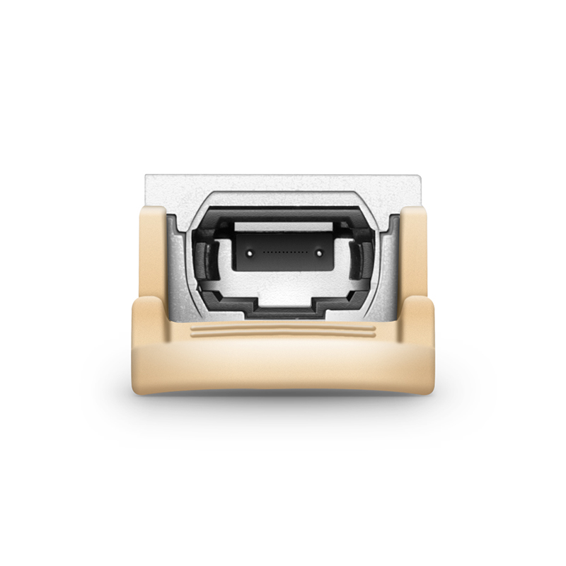
You can see the 12 fiber contacts, plus male pins, inside the optic.
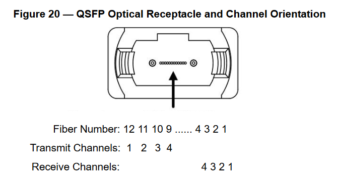
On 40G-SR optics running in 40Gbps mode (not 4x10G breakout mode), 4 lanes of 10Gbps ethernet signals are transmitted on 4 fibers in each direction. According to the MSA, “The four fiber positions on the left (fibers 12, 11, 10, 9) are used for the optical transmit signals (Channel 1 through 4). The fiber positions on the right (fibers 4, 3, 2, 1) are used for the optical receive signals (Channel 4 through 1). The central four fibers (5, 6, 7, 8) may be physically present.” The reason so many fibers are needed is because each 10Gbps signal is transmitted as an 850nm wave, and you can not have the same wave transmitted multiple times on the same fiber (today) without the signals interfering with each other.
100G-SR optics work the same way, except instead of four 10Gbps lanes, they use 4 25Gbps lanes transmitting across 4 fibers in each direction.
Legally I wouldn’t advise you to do this, but you can verify this by connecting an MPO cable to an active, transmitting pluggable optic and looking at the other end of the cable. You’ll see the 4 10Gbps lanes transmitting red light on either fibers 12-9 of that side of the cable. Due to the keying, fibers 12-9 will be on the opposite side on the other end of the cable.
Single Mode and Multimode Breakout Optics/Harnesses
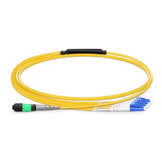
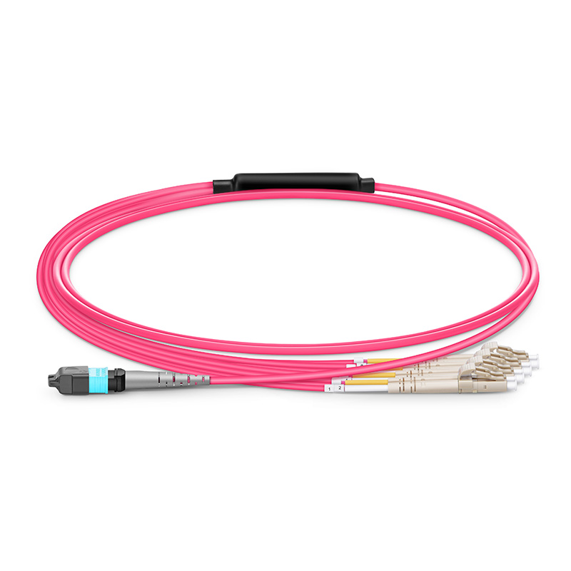
MPO cables are also commonly used on breakout optics and breakout harnesses. The most common use case is 40G LR/SR optics being broken down into 4 separate 10G interfaces. One side of the connection is an MPO-12 connector and the other side is 4 pairs of duplex LC fiber connectors.
For a 40G-LR breakout connection, you actually have to use a specific PID to break them out. Usually, this is a “PLR4” optic, since a standard “40G-LR” optic uses LC connectors and a “PLR4” optic uses MPO connectors. These PLR4 optics are used commonly in internet peering to connect 10G PNIs between entities as organizations move away from 10G SFP+ optics toward 100G QSFP28 optics.
For 40G-SR breakout (much less common) you can use a standard 40G-SR optic because that optic already uses an MPO connector. Typically you just apply a configuration to the box that the optic is plugged into to change it from 40G “full” mode to 4x10G breakout mode.
Breaking out 10G interfaces from a 40G interface allows us to use 40G QSFP interfaces rather than individual 10G SFP+ interfaces. We do this because it allows us to run denser higher speed equipment - the denser we can run equipment the more we can save on costs.
One of the main drawbacks of breakout optics is that your failure domain is expanded. 4 links are now sharing the fate of a single pluggable optic rather than each link having its own pluggable optic. If the pluggable or cable fails, 4 links are taken down instead of 1 single link. If you terminate the breakout optic onto a QSFP28 port you are also only using 40% of the available bandwidth of the port, another drawback.
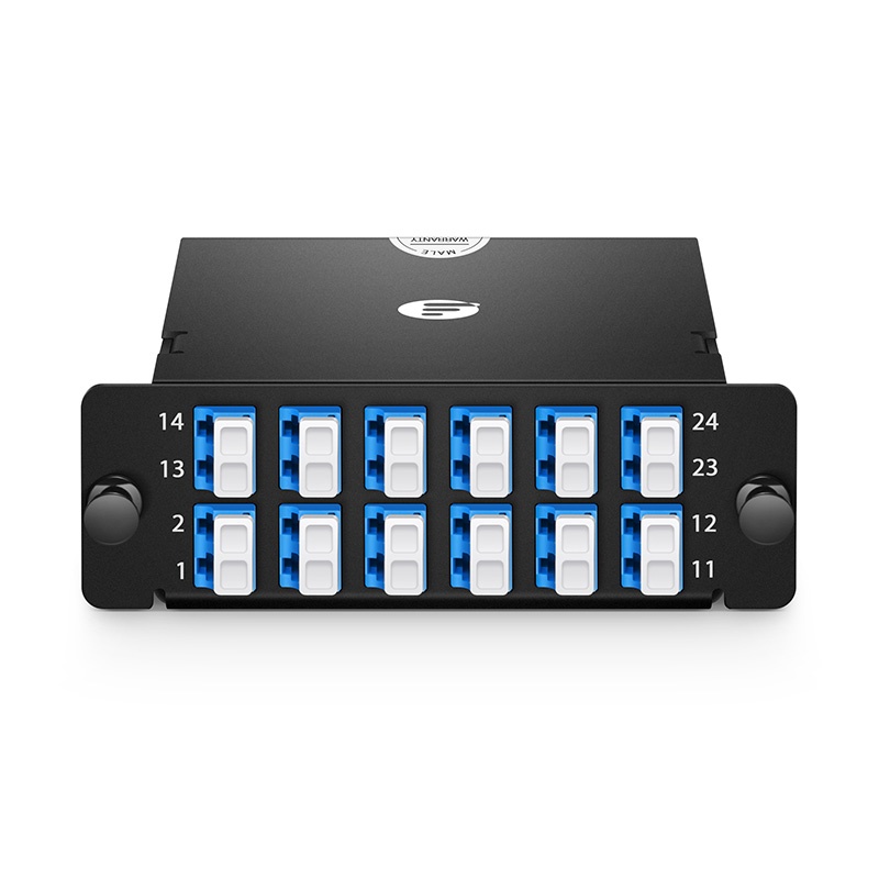
Typically, you can break out either with a cable directly or through a panel. If you’re connecting to a third party, or a separate rack a panel is usually preferable to keep things cleaner and to have a specific point of demarcation that isn’t an optic or a cable. Some panels simply terminate LC connectors,
DCI - Data Center Interconnect & Fan Out
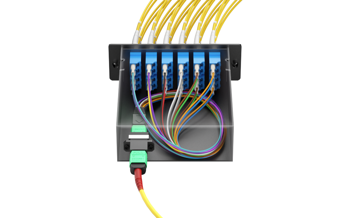
In the same way that MPO cables can be used to break out 40G to 10G, you can also break out each pair (12 total) of the 24 fibers bundled into the cable into LC connectors and run whatever signal you want on the cable itself. This is super useful to be able to run multiple cross connects over a single physical cable between racks or spaces in a data center. It is much more convenient to run a single MPO cable than 24 individual pairs of fiber between locations.
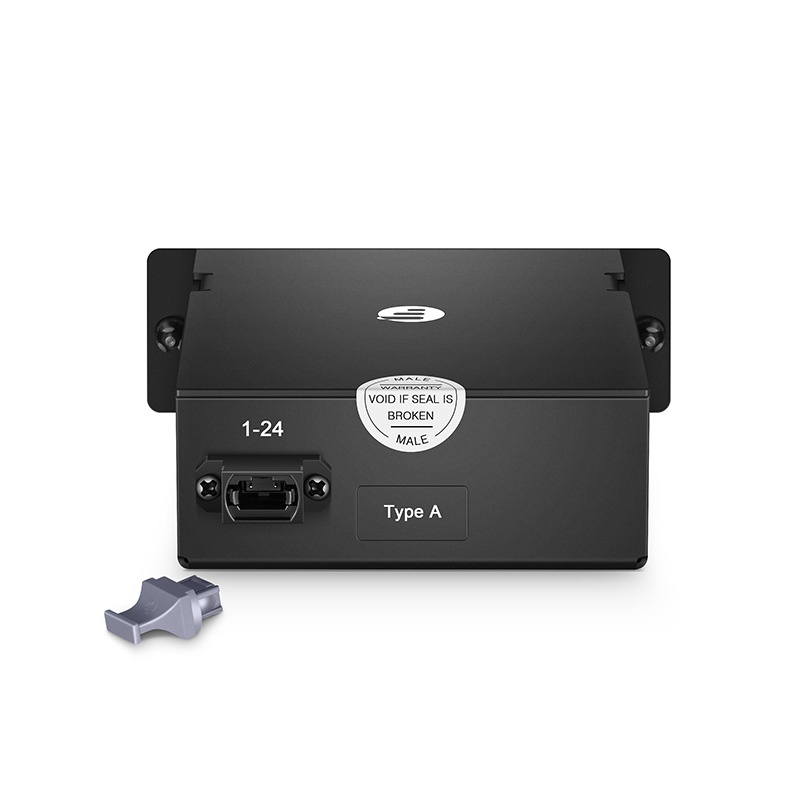
To connect these together, you run a single MPO-24 female to MPO-24 female cable between your racks/rooms/data centers, and connect them to the back of a breakout casette/panel on each end. You then get 24 fibers (12 pairs) between the two locations, and all you had to do was run one cable.
Fan out has been used for decades in Optical Networking, going back to the early 2000s you can see them present on multiplexing and de-multiplexing cards on Cisco 15454 optical gear.
These panels allow dense inter-rack connectivity at an affordable price range.
I’m sure there’s many other applications of MPO cables, but these are the ones that immediately came to mind for me. I’ll probably continue to update this post in the future with more details.
All images in this post came from FS.com. They offer affordable and easily accessible MPO cables and are a decent source for glass network gear.